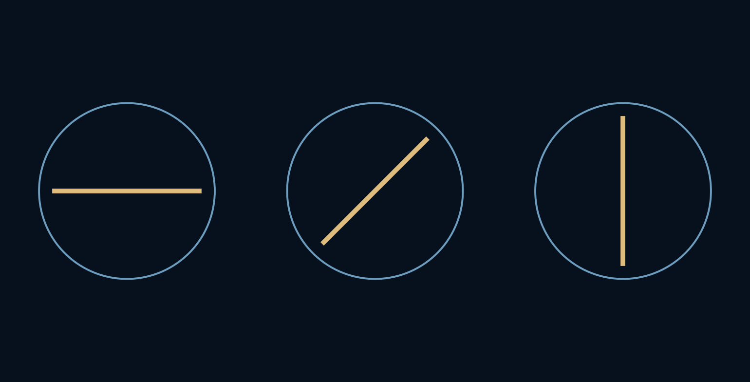
Why can two clear-looking sheets become nearly opaque together?
Brightness and colour are familiar properties of light. Polarization adds another: the direction in which its electric field oscillates. A pair of ideal polarizers turns that invisible direction into a visible change in brightness. A third sheet creates a result that is even more surprising, provided we keep careful track of what each sheet changes.
A filter changes the light that reaches the next filter.
A direction across the path
Light is an electromagnetic wave. For a plane wave in free space, the electric field oscillates across the direction of travel. In linearly polarized light, that oscillation follows one fixed transverse direction. The transmission axis of an ideal linear polarizer selects the component aligned with its own direction.
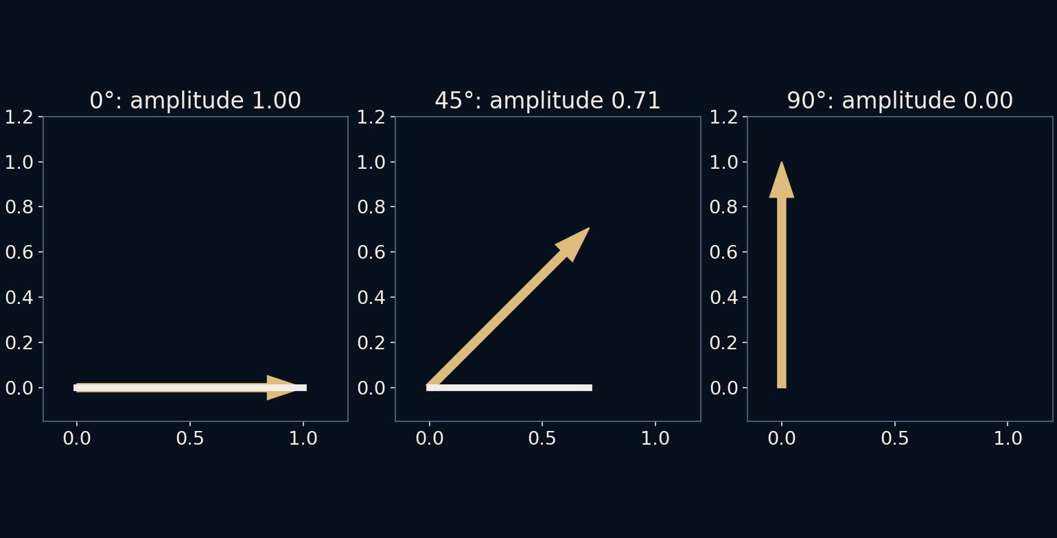
It helps to picture an arrow projected onto a line. Rotate the line away from the arrow and the retained component becomes smaller. At a right angle it is zero. The arrow drawing concerns field amplitude, however, while the brightness calculation uses intensity, which is proportional to amplitude squared under the stated wave conditions.
The square makes the curve
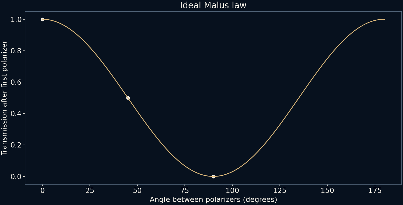
Malus's law says that transmitted intensity equals the incoming linearly polarized intensity multiplied by the square of the cosine of the relative angle. Parallel axes transmit all of that ideal input. At 45 degrees, half remains. At 90 degrees, none remains in the ideal calculation.
Our graph measures every output relative to the light already emerging from the first polarizer. That reference matters. Saying that a 45-degree analyzer passes half does not mean that half of the original unpolarized beam necessarily reaches the end. We must account separately for the first sheet before applying the next factor.

The extra sheet that lets light through
An ideal first polarizer transmits half the intensity of unpolarized light, averaged over its changing directions. Put a second polarizer at 90 degrees and the model gives zero. Now insert another polarizer between them, with its axis at 45 degrees. Light appears at the end of the three-sheet arrangement.
The fractions multiply: one half at the first sheet, one half at the middle sheet and one half at the last sheet. The final intensity is one eighth, or 12.5%, of the initial unpolarized input. The middle sheet absorbs some light but also establishes a new polarization direction for what continues, changing the final sheet's input.
More transmission is not extra energy
The three-sheet result can sound as if inserting an absorber creates light. It does not. The comparison is between two different optical arrangements. In the crossed pair, the last sheet rejects the first sheet's polarization. In the three-sheet case, the light arriving there has a different direction and a reduced intensity.
Every stage in the calculation transmits at most the intensity incident on that stage. The output never exceeds the input. The effect is a reminder that a sequence of operations cannot always be understood by assigning each component an independent percentage loss without considering how earlier components change the state being passed along.
A real filter has a less perfect boundary
Real polarizers can absorb some of the nominally transmitted component and leak some of the rejected component. Their response may depend on wavelength and angle of incidence. Scattering, reflections and the polarization already present in a scene can complicate an experiment that looks simple on paper.
Polarizing sunglasses and photographic filters use related principles, but this model does not predict the behaviour of any particular product. LCD screens can also have polarized output, so rotating a filter in front of one may change its brightness dramatically. The exact orientation and result depend on the screen, rather than on a universal rule for all displays.
Keep the reference with the number
The most useful part of the exercise is learning to attach every fraction to an incoming beam. Half after the first sheet, a quarter after the next and an eighth after the third are stages of one specific arrangement. They cannot be swapped into a different arrangement without checking the axes again.
Polarization gives a beam more structure than a brightness meter alone describes. Two equally bright beams can respond differently to the same filter because their field directions differ. Once that hidden state is included, the apparently paradoxical extra sheet becomes an ordinary sequence of projections and intensity changes.
Further reading
OpenStax: Polarization ↗OpenStax: Electromagnetic waves ↗Original documentation and useful background.